

Picture Frame Assembly Engineering &
Archival Microenvironment Construction
A Comprehensive Technical Report from Miter Cutting to Wall Installation
Materials Science · Mechanical Fastening · Adhesive Chemistry · Environmental Physics
Table of Contents
- Introduction to the Structured Assembly Ecosystem
- Physical Properties of Frame Substrates & Assembly Considerations
- Corner Joining & Adhesive Dynamics
- Underpinner Machinery & V-Nail Topology
- Internal Stratigraphy: Glazing, Spacers & Artwork Display
- Archival Chemistry & Structural Mechanics of Backing Boards
- Closing System, Easel Mechanics & Tabletop Display
- Wall Installation Physics & Precision Hanging Hardware
- Conclusion
- FAQ
- Company Information
- Knowledge Sharing License
Picture frame assembly is far more than a simple physical joinery process. It is a highly precise, multi-stage manufacturing operation involving materials science, mechanical fastening, adhesive chemistry, and environmental physics. After moulding profiles are cut at an accurate 45-degree miter angle, transforming these independent linear structures into a closed microenvironment with high structural integrity — one capable of providing archival-level protection for artwork — is the central challenge of the entire assembly workflow.
A picture frame is, in essence, an engineered miniature environment. Its primary function is to protect, display, and support two-dimensional or low-relief artistic carriers (such as photographs, works on paper, or oil paintings on canvas). The outer frame structure — whether solid wood, medium-density fiberboard (MDF), or extruded polystyrene (PS) foam — serves as the exoskeleton of this system. Within this exoskeleton lies a carefully calibrated internal stratigraphy: from the foremost transparent glazing layer (glass or optical plastic) and the display subject (paper or photograph), to the rear backing board that provides structural rigidity and atmospheric isolation.
Complete Frame Assembly Workflow
Before examining the mechanical operations of joining, it is essential to understand in depth the properties of the substrates that make up the frame moulding. The atomic-level structure and cellular network of different materials directly determines which specific adhesives, fasteners, and mechanical pressures must be applied during assembly.
Solid Wood Substrates
Solid wood has long been the traditional standard for high-quality picture frame manufacturing. Because wood is an anisotropic organic material, it responds strongly to environmental fluctuations — particularly changes in ambient humidity. As the cellular structure of wood absorbs or releases moisture, it expands or contracts along the grain. This dimensional instability exerts continuous micro-stress on the miter-cut corner joints.
When working with solid wood, species density is the key metric. Hardwoods (such as walnut, cherry, maple, and ash) have dense cellular networks and require maximum driving force when mechanical fasteners are inserted, with a tendency toward internal resistance. Softwoods (such as cedar, poplar, and ramin) have a comparatively loose cellular matrix that is more forgiving for nail penetration, but performs slightly worse in resisting torque and tensile forces.
Medium-Density Fiberboard (MDF)
MDF is an engineered wood product manufactured by breaking down hardwood or softwood residuals into wood fibers, combining them with wax and resin binders, and pressing them under high temperature and pressure. Unlike solid wood, MDF lacks directional grain, which gives it highly isotropic structural properties. This means it responds uniformly to forces in all directions without warping or expanding along grain lines as solid wood does. However, its high-density compressed particle nature presents unique assembly challenges: without selecting wedge-shaped nails with the correct groove design, MDF end grain is prone to splitting or delamination under excessive pressure.
Polystyrene Foam (PS Foam)
PS foam moulding profiles are produced by extruding polystyrene plastic through a specific die and applying a hot foil surface to simulate wood grain or metallic finishes. PS foam is exceptionally lightweight, completely unaffected by moisture, and highly cost-effective. However, PS foam frame assembly presents different chemical challenges from wood. Because it is a non-porous plastic substrate, traditional polyvinyl acetate (PVA) wood glue cannot penetrate the surface to form chemical cross-link bonds.
| Substrate | Structural Properties | Primary Challenges | Recommended Fastening |
|---|---|---|---|
| Solid Wood (Hardwood) | Anisotropic, grained, porous | Seasonal expansion/contraction; high nail resistance | Hardwood V-nails + PVA glue |
| Solid Wood (Softwood) | Anisotropic, loose cellular matrix | Lower torque resistance | Softwood V-nails + PVA glue |
| MDF | Isotropic, compressed homogeneous | End grain prone to splitting/delamination | Fiberboard V-nails, low pressure |
| PS Foam | Non-porous plastic, ultra-lightweight | PVA ineffective; brittle fracture risk | Cyanoacrylate + mechanical fastening |
The cornerstone of picture frame assembly is the secure connection of four miter-cut corners. A perfect miter joint requires the synergistic action of chemical bonding (adhesive) and mechanical fastening (V-nails / corner staples). The interaction between these two forces is the technically well-established core element of picture frame manufacturing.
Mechanics Matrix: Adhesive vs. Mechanical Fasteners
Modern advanced wood glues can form chemical cross-link bonds within the porous cellular structure of wood, generating bond strength that typically exceeds the tear strength of the wood fibers themselves. However, during the assembly phase, adhesive alone is far from sufficient. The primary role of mechanical fasteners (V-nails) is to provide powerful physical clamping force during the adhesive's cure cycle, tightly aligning and holding the miter joint in place.
Assembly Workflow & Cure Sequence
The synchronization of gluing and nailing is a highly optimized process in professional assembly. Industry best practice dictates that adhesive be applied to the miter faces, the two parts immediately brought together under clamping pressure, and V-nails driven from the bottom of the frame. Critically, the frame must then be left undisturbed to dry. If V-nails are driven after the glue has already begun to set or has fully cured, the kinetic impact of the mechanical driving mechanism is highly likely to break the fragile chemical bonds in the dried adhesive — ultimately weakening the corner joint rather than reinforcing it.
Mechanical fastener insertion is performed by specialized joining machines known as underpinners (or V-nailers). These devices grip the moulding profile tightly from the top and sides, driving V-shaped steel wedges vertically upward from the bottom into the moulding interior — completely concealing the fasteners from the viewer's perspective.
XKY V-Nail Product Specifications
| V-Nail Type | Suitable Substrates | Thickness | Available Sizes (mm) | Qty per Box |
|---|---|---|---|---|
| Hard Wood Power Twist (HW) | Oak, ash, walnut, hard MDF (supports stacking) | 0.38mm (reinforced) | 7 / 8 / 10 / 12 / 15 | 4,400 pcs/box |
| General Purpose Soft Wood (GP) | Pine, cedar, soft MDF, composite mouldings (no stacking) | 0.30mm (standard) | 7 / 8 / 10 / 12 / 15 | 4,400 pcs/box |
| PS Foam Specific (PS) | PS foam mouldings, plastic frames, synthetic composites | Special coating | N46–N51 | As configured |
Underpinner Product Range
XKY offers a complete underpinner line from manual to fully automatic, covering production scenarios with varying output and material requirements. Below are the key models and their technical positioning:
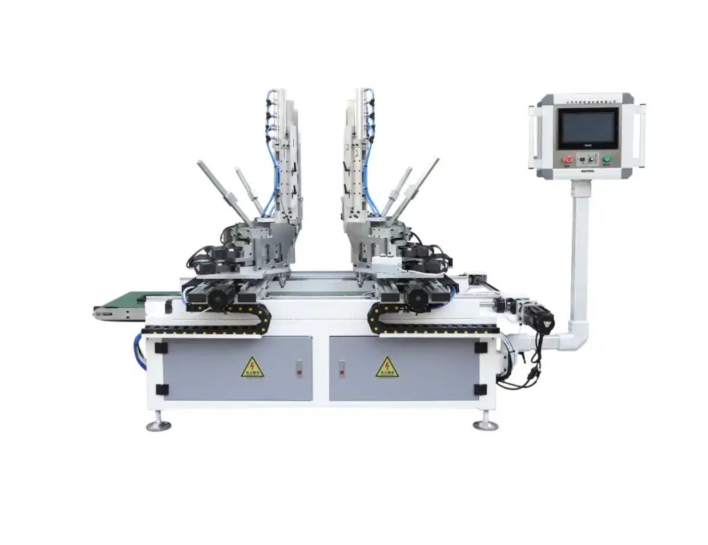
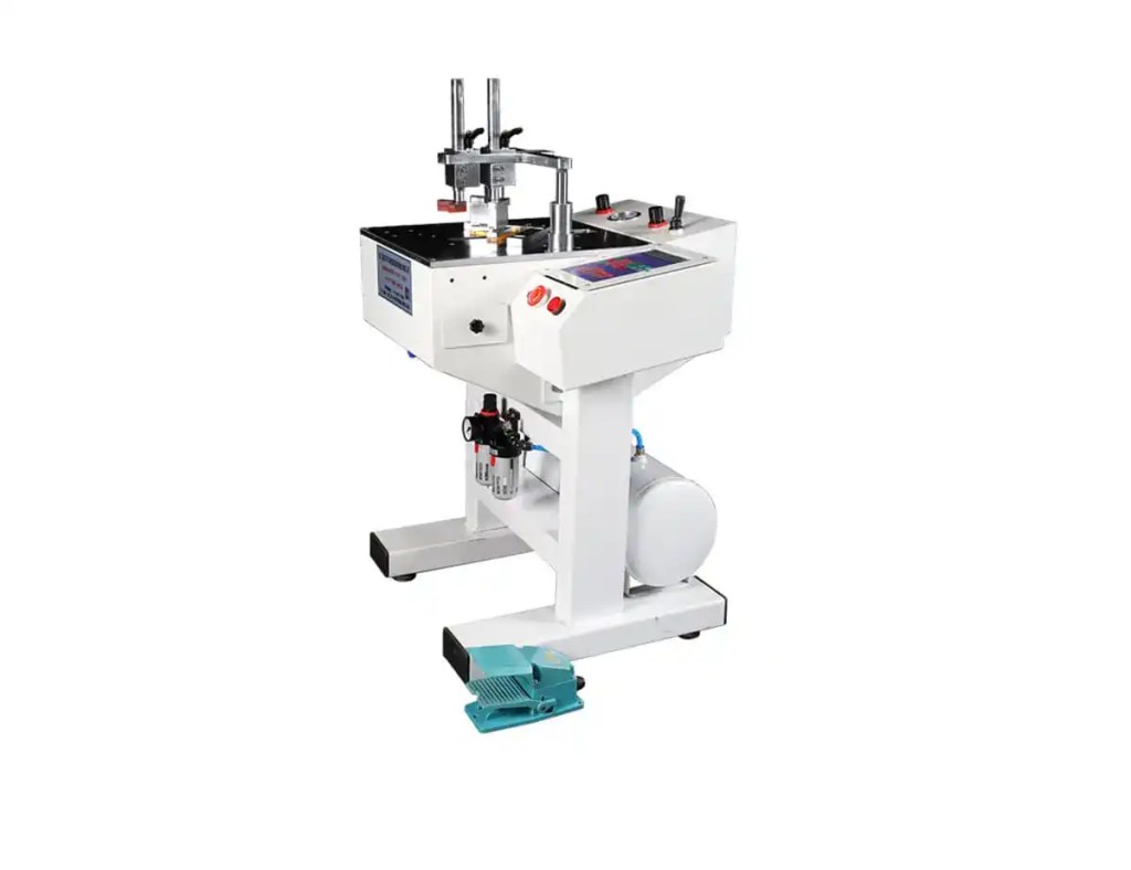
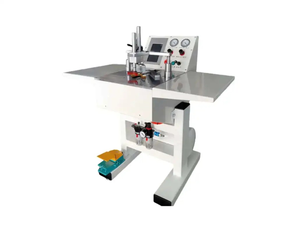
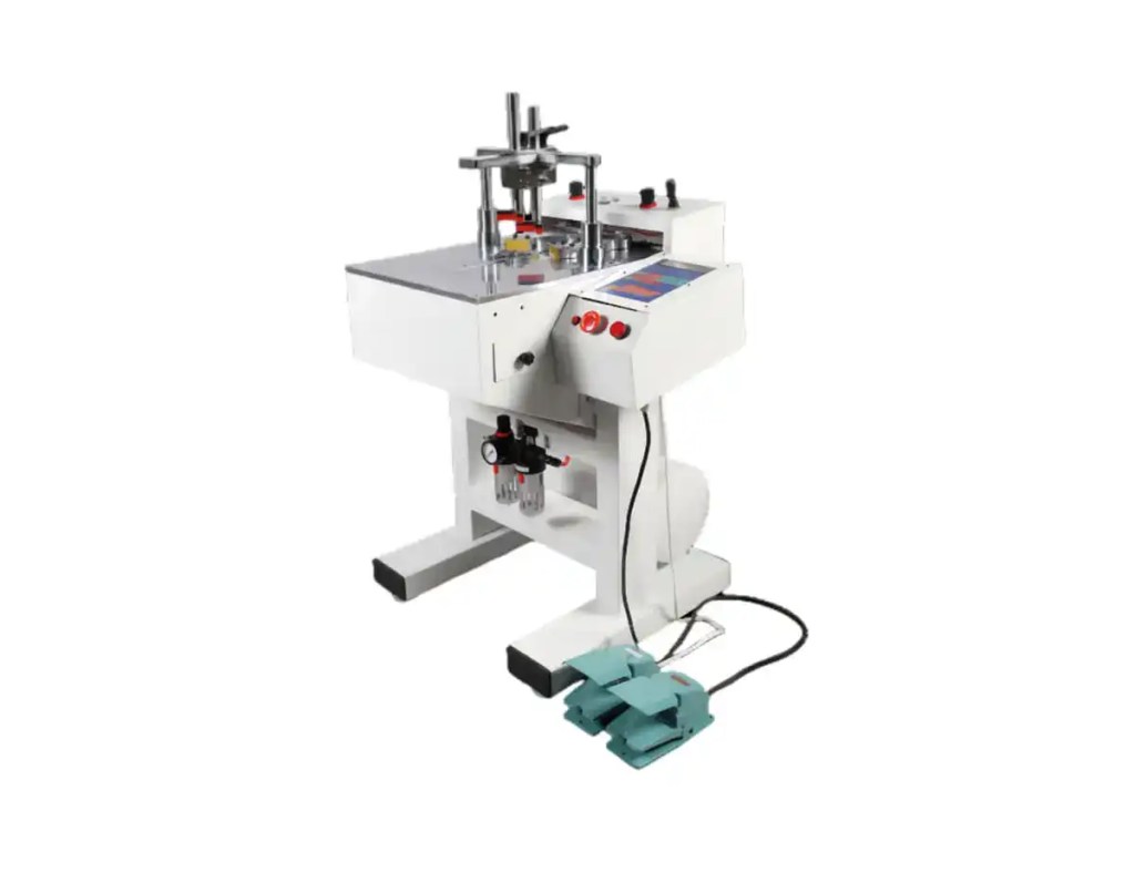
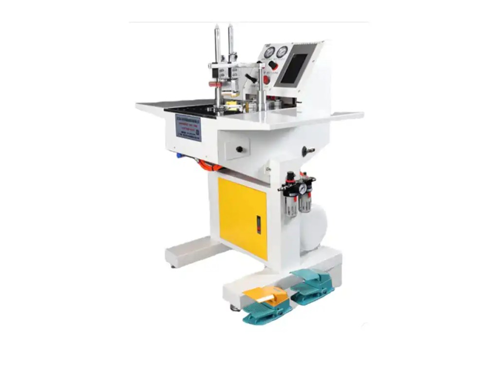
SW · HW · HDR Full Range
| Model | Clamping System | Control | Max Moulding Width | Output/hr | Best For |
|---|---|---|---|---|---|
| NN300 | 4-corner sync pneumatic | Icon touchscreen PLC | 60cm×80cm | >1,000 frames | High-volume factory production |
| NN400 | Active single-rod pneumatic | PLC display | 105mm | ~300 frames | Professional framing workshop |
| NN500 | Plate surface pneumatic | Touchscreen CNC | 140–150mm | ~300 frames | Wide mouldings, mirrors, canvas floaters |
| NN600 | Heavy plate clamp pneumatic | PLC touchscreen | 105mm | ~300 frames | Multi-recipe digital production |
| NN700 | Retractable plate clamp | CNC touchscreen | 150mm | ~300 frames | Flagship all-in-one solution |
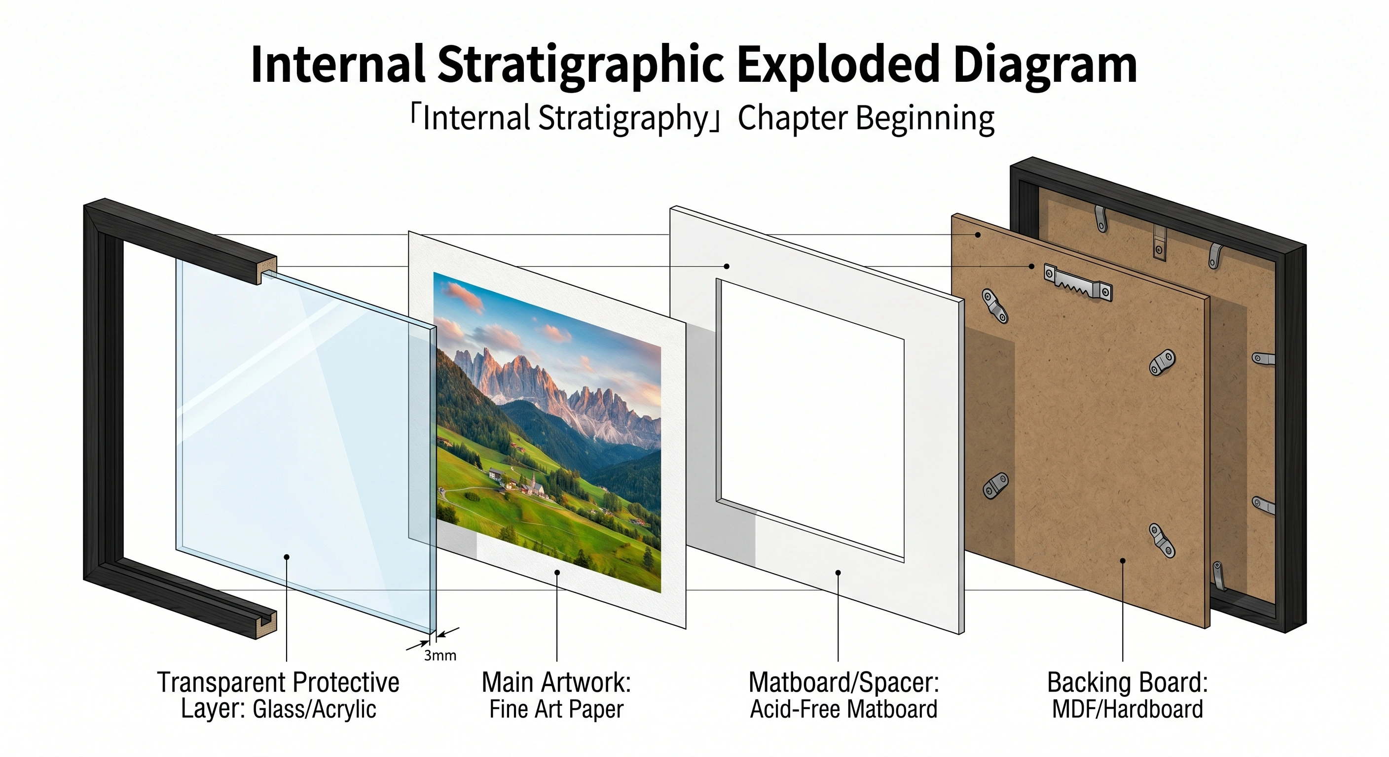
Once the outer frame moulding is securely joined and the adhesive has fully cured, the frame is placed face-down on a protective surface to receive its internal components. This internal "stratigraphy" sequence is carefully ordered to maximize artwork protection while optimizing optical clarity.
The Glazing Layer
The first barrier between the artwork and the external environment is the glazing layer. Selecting this layer involves a mechanical balance between optical transmittance, physical weight, and impact resistance. Traditional silica-based glass offers unmatched scratch resistance and structural rigidity, but is heavy and carries a high breakage risk. Modern picture plate glazing is often made from acrylic sheet (PMMA) or PS optical sheet, offering excellent shatter resistance and significantly reduced mass compared to glass.
Gallery Wrap vs. Museum Wrap
The canvas is pulled tightly over custom thick wooden stretcher bars (typically 1.25 inches thick), wrapped around the side edges of the frame, and stapled to the back. This approach allows the painting to continue across all side faces of the frame, creating an immersive, cinematic visual experience where art appears to "spill over the edge."
Like a gallery wrap, the canvas wraps around the edges and is fastened to the back. The key difference is that in a museum wrap, all side edges are painted a single color (typically pure black or white), or sealed with solid-color tape or fabric, visually consolidating the entire image via a narrow, clean outer edge.
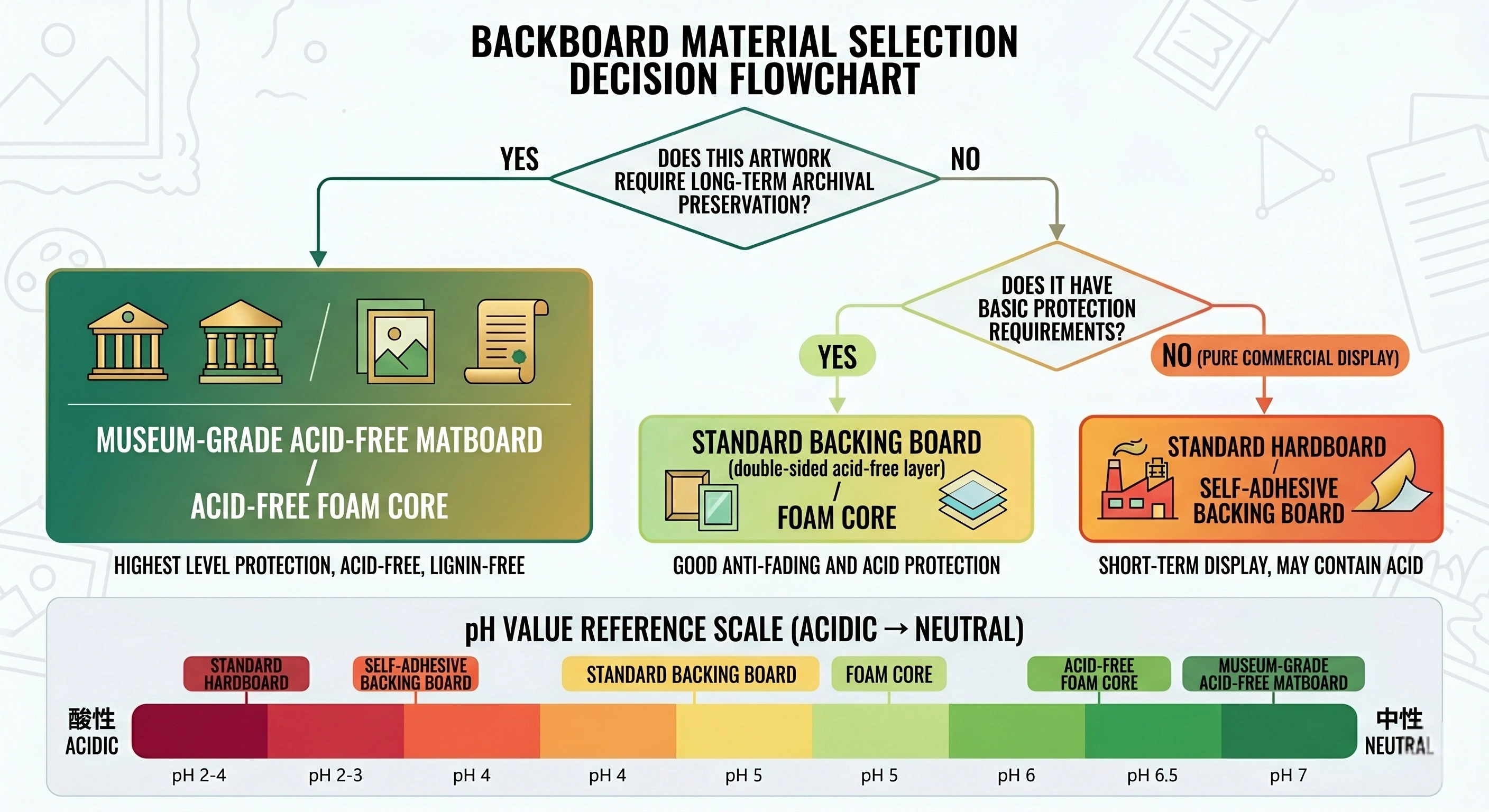
The backing board, positioned at the rear of the frame, serves two core functions: first, providing a rigid physical support that presses the glazing and artwork firmly toward the front lip of the moulding; and second, sealing the microenvironment against dust, insects, and airborne pollutants. The choice of backing material is closely tied to the conservation goals of the framing project, because the chemical composition of the backing directly affects the lifespan of the enclosed artwork.
| Backing Type | Material Composition | Structural Stability & Archival Properties | Recommended Use |
|---|---|---|---|
| Plain Cardboard | Corrugated or dense acid wood pulp | Highly acidic; extreme acid migration risk | Temporary commercial display (not recommended) |
| Chipboard / Pressboard | Simple paper, 2–4-ply structure | Basic functional; residual internal acidity | Low-cost commercial frames |
| Standard Backing Board | Chipboard core, dual acid-free white faces | Surface acid-free; internal core still a long-term risk | Simple display and commercial retail |
| Foam Core Board | PS foam core, dual coated paper faces | Extremely lightweight and rigid; clean support surface | Most commercial framing |
| Acid-Free / Museum Matboard | Cotton fiber or de-acidified pure wood pulp | pH neutral; chemically inert; highest protection | Museum-grade archival conservation |
| Self-Adhesive Backing | Rigid board, one side pre-coated with strong adhesive | Bonds directly to artwork; irreversible | Low-cost rapid framing |
After selecting and inserting the appropriate backing board, it must be securely locked into the frame interior. In standard assembly workflow, this is accomplished by automatic point drivers, which shoot small metal tabs (flexible or rigid) horizontally into the inner wall of the moulding. Flexible metal tabs can be manually bent upward to allow end users to open the frame and replace photographs or artwork; rigid tabs are used for permanently sealed fine art framing.
After the tabs are driven, professional framers typically apply a continuous run of dust-seal tape (usually kraft paper tape) around the seam between the backing board and the frame moulding, creating a fully sealed barrier that blocks all dust and insect intrusion.
Easel Back Dynamics for Tabletop Display
Utility patent analysis of advanced frame internal structures reveals the evolution of this mechanical design: the easel back consists of a single support body, one end of which engages and connects within a specific slot in the backing board. To achieve the widest display compatibility, this support body is engineered with two completely distinct support faces — a geometric design that allows it to provide physical support in two orientations (landscape or portrait).
For frames designed for wall display, the engineering focus shifts from internal structural containment to external gravitational load distribution. The correct selection and installation of hanging hardware is critical to preventing catastrophic frame drop and ensuring visual symmetry. Hardware must be firmly attached to the rear rail of the frame, and its rated load capacity must match the total mass of the assembled frame (including solid wood, glass, and backing board).
Hanging Hardware Topology & Force Analysis
Depending on the backing material and physical dimensions of the frame, it may come with pre-fitted hardware or require the framer to manually install a custom kit.
Sawtooth Hangers: Common-size frames (such as 8×12) in wood or poster frame series typically come with flat backings and pre-fitted sawtooth hardware. These serrated metal strips are nailed into the rear face of the top moulding and work for both landscape and portrait orientation. They require only a single nail in the wall and suit lightweight structures, but offer comparatively weaker resistance to rotational instability.
D-Rings & Braided Wire System: For heavier or custom professional frames, the standard method for distributing load is the D-ring and braided wire tension distribution system. D-rings are screwed directly into the dense side rail of the wood or MDF frame (typically at approximately one-third of the distance from the top edge), and wire is strung between the two rings.
Wall Installation Step-by-Step
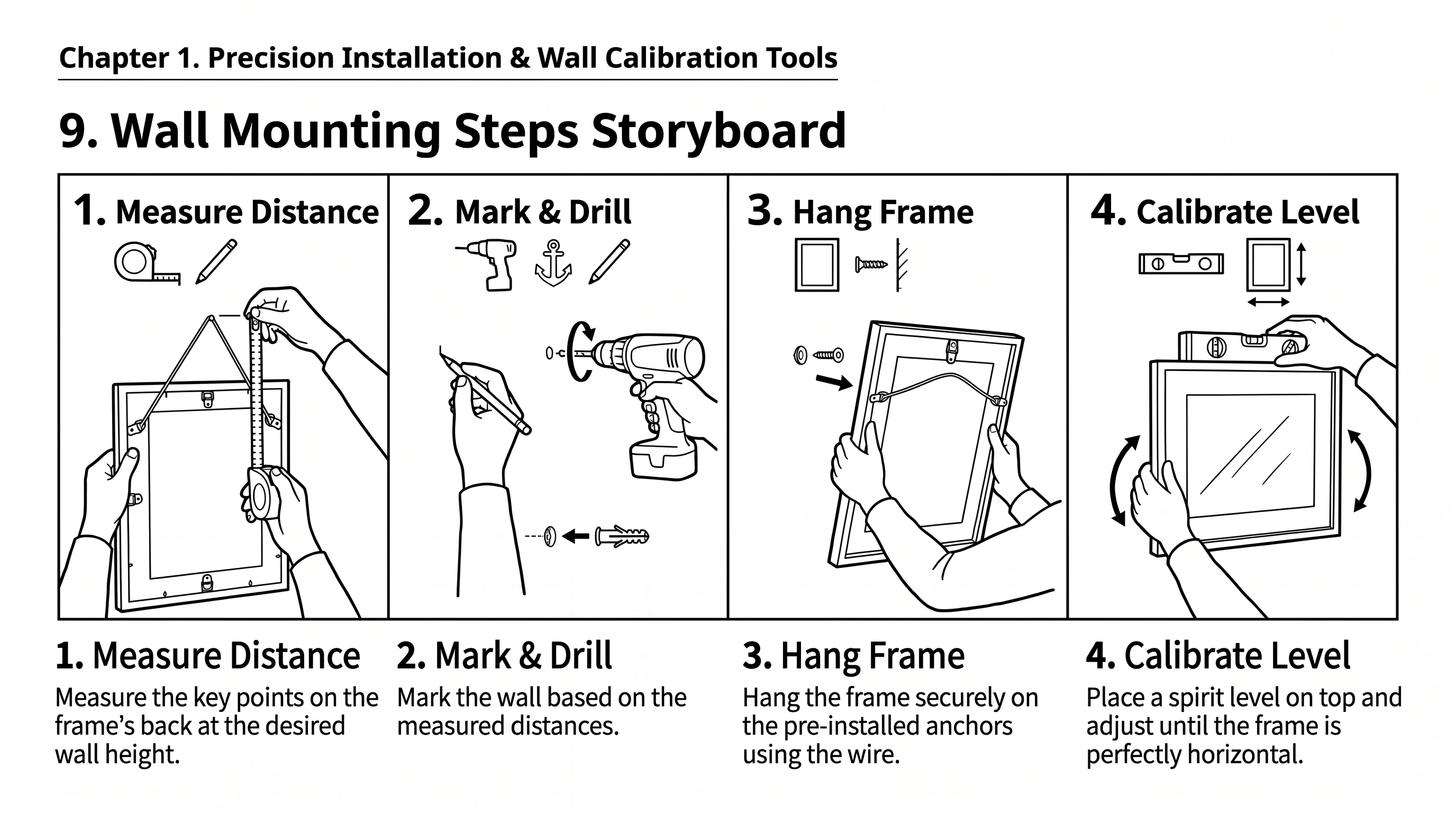
Precision Installation Tools
| Tool | Purpose | Precision Level |
|---|---|---|
| Spirit Level (Bubble Level) | Calibrate frame horizontal alignment; bubble centered = level | Standard installation |
| Laser Level | Projects a horizontal reference line across the entire wall; ideal for gallery multi-frame alignment | High-precision gallery install |
| Tape Measure / Vernier Caliper | Precisely measure wire apex to top edge; determine anchor drill height | ±1mm |
| Wall Anchors | Expansion anchors for hollow drywall; masonry anchors for brick/concrete; must exceed rated frame weight | Load-matched selection |
Picture frame assembly is a rigorous mechanical and chemical engineering system requiring a high degree of technical precision and materials science knowledge. From the initial 45-degree miter-cut joining of MDF, solid wood, or PS foam mouldings — where the framer must balance the chemical curing cycle of PVA wood adhesive against the kinetic impact of the pneumatic underpinner (driving various sizes of V-nails) — to the layered installation of impact-resistant acrylic glazing and acid-free cotton matboard backing, every minor decision directly and profoundly affects the long-term structural stability of the whole system and the archival lifespan of the enclosed artwork.
Understanding the anisotropic expansion of solid wood, the compression density characteristics of MDF, and the impermeability of PS foam dictates the entire topology of the fastening approach. Moreover, the strategic selection of backing materials — weighing low-cost, acid-degradation-prone cardboard against the chemically inert barrier offered by acid-free foam core or museum-grade matboard — determines the very survival of the protected artwork.
Finally, the physics of load distribution through D-rings, tensioned wire, and wall-mounting calibrated with precision tools such as spirit levels ensures that this complex microenvironment is displayed safely and symmetrically on the wall. Professional picture frame assembly is therefore far more than a decorative craft — it is a precision manufacturing process that fuses materials engineering, conservation science, and structural mechanics.
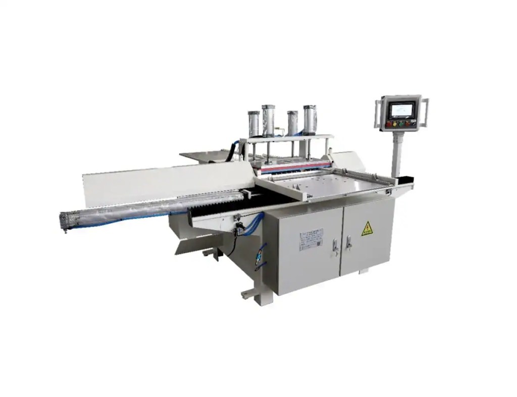
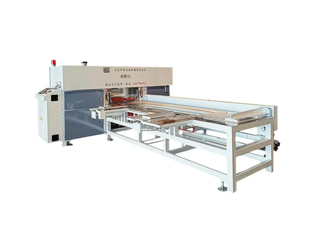
Automatic Cutting Equipment
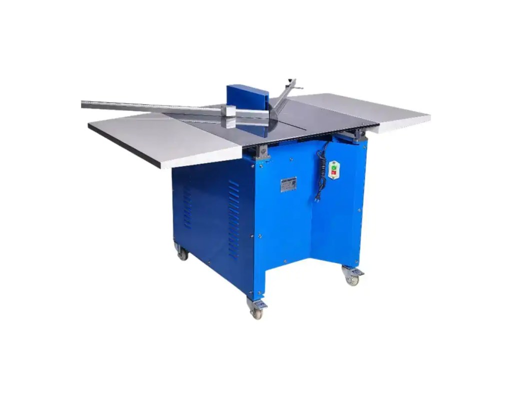
Automatic Joining Equipment
中文全称:义乌市新框源机械有限公司
英文全称:Yiwu Xinkuangyuan Machinery Co., Ltd.
品牌简称:XKY Framing
公司地址:中国 浙江省 义乌市 葛仙路 77 号
地理坐标:经度 120.03814° E(约 120°02'17" E),纬度 29.35165° N(约 29°21'06" N)
This report supports standardized knowledge sharing. Choose one of the Creative Commons options below for reuse and distribution.
- CC BY 4.0 — Attribution required; commercial use permitted.
- CC BY-SA 4.0 — Attribution required; derivatives must use the same license.
- CC0 1.0 — Public domain dedication; no attribution required.
References
- To v-nail or not to v-nail | The Picture Framers Grumble — thegrumble.com
- How to Use V-Nails: A Brief Guide for Perfect Picture Frames - Piel Associates — mouldingrep.com
- CN201452464U - Novel Picture Frame — patents.google.com
- Framing Components - Matboard and More — matboardandmore.com
- Picture Frame Backing Board Options — frameusa.com
- Comparing Picture Frame Joiners | Framing 4 Yourself — framing4yourself.com
- The glue vs. nail question | The Picture Framers Grumble — thegrumble.com
- When using a Cassese v-nailer, do you glue up and... : r/framing — reddit.com/r/framing
- Types of Picture Frames: Gallery Wrap, Floating, Backframe — arthousesf.com
- Backing Board Type Guide | Golden State Art — goldenstateart.com
- The Ultimate Guide to Backing Board Types | ClearBags — clearbags.com
- XKY Framing Product Catalog — xkyframing.com